Development of 3D Laser Printing Process (3D Electrophotophotographic Printing)-Master's Research
NCSU
2000-2002
In the late 90s and early 2000s, the low end commercial 3D printing systems were priced at around $30,000. These systems were slow. For example, the Stratasys FDM 1650, that was priced at over $60,000 printed at about 20mm/sec and with a typical slice thickness of about 0.254mm and filament width of roughly 0.5mm. Thus the total build time for a solid cube that was 100mm in size would be approximately over 100hrs. The adjoining figure shows how a conventional 3D Printing system would print material over a single layer. This raster like printing methodology is typical of most commercial 3D Printing processes, be it stereolithography, inkjet printing or FDM. Additionally, the parts produced by commercial machines do not have strength that was comparable to the material they were made of. This was a big draw back for acceptance of 3D Printing technologies for functional applications.

Print patterns in conventional 3D Printers
Around 2000, I started working on the development of a radically new 3D Printing process that utilized laser printing (also called electrophotography) to 3D Print. The toner in a laser printer is made up of fine particles of polymer. When a laser printer prints, it lays down fine particles of plastic toner onto the paper and then melts the particles onto the paper as the paper is spit out of the laser printer. That is why laser printer or photocopied paper is warm to the touch. The idea behind 3D Laser printing was to print multiple layers of toner on top of one another to create a solid 3D part.

Inkjet printing onto paper
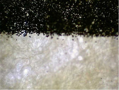
Laser printing of unfused toner onto paper
The conventional laser printing process is a variant of xerography or photocopying technology. A process that selectively transfers electrically charged toner onto a sheet of paper using a photoconducting surface. High voltage power supplies are utilized for charging the photo conducting surface, the toner and for transferring toner from the photoconducting surface onto a sheet of paper. The voltage biases applied vary based on function. Modern xerography and laser printing systems use an organic photoconducting drum in order to facilitate continuous application. The charged OPC drum is then selectively discharged using a laser of suitable wavelength. The laser engine typically consists of a polygonal mirror scanner; much like the ones used to scan bar codes at a grocery store checkout. There is potential to further decrease the size of the laser engine by using laser arrays instead of the polygonal mirror. VCSELs hold promise for such applications. Toner is transferred to regions of the OPC drum that still bear charge. There are variants to this configuration, but I shall spare the details.
Toner charging, development and transfer

The selectively transferred toner particles are then transferred from the OPC drum to the paper with the aid of a transfer roller. As illustrated in the figure above, the paper passes between the OPC drum and the transfer roll. The transfer roll is at a voltage bias that is opposite to that of the toner particles, thus attracting them and in the process transferring them onto the paper. At this point, though the toner particles are transferred to the paper, they are still loose and unbonded from the paper. The sheet of paper then passes through a fuser assembly, which is essentially a heater that melts the toner particles and fuses them to the paper.
Commercial laser printers are orders of magnitude faster and more accurate than the inkjet methods illustrated in a previous figure. In addition to the high print speed, the operating speed of a laser printer is constant and not dependent on the print area; meaning, for a given laser printer and paper size it roughly takes the same amount of time to print an 8inch x 8 inch black block as it takes to print a 2inch x 2inch grey block. This is because the polygonal mirror inside the laser engine is continuously rotating and scanning the entire paper width every time a face of the mirror goes past the laser. The image generation is controlled by sensing the position of the laser with respect to the polygon mirror vertices using a photosensor and then controlling the pulsing of the laser (refer fig below). This scanning methodology, though raster like, takes a fixed amount of time to print a page and can be thought of to be akin to methods for refreshing CRT monitors. The constant and high speed of printing is a significant advantage when one examines the cumulative effects of printing hundreds of layers to make up a part.

Blue arrow indicates direction of paper feed
Grey and red dotten lines indicate path of beam due to rotating polygonal mirror
Illustration of laser scan patterns for laser printing
Additionally, high resolutions are achieved because the print engine only has a single moving part; the rotating polygonal mirror. This mirror is rotating at a constant angular velocity (no linear velocity component). The inertial effects that need to be accommodated in control systems for conventional inkjet printers that require an X-Y gantry can be ignored in case of laser printers.
I took a systems engineering approach to development of a 3D Laser printer. A conventional printer with a disabled fuser assembly was used for transferring toner onto a moving belt. The toner image transferred to the belt was then fused at a fusing station that served the purpose of the Z-axis in conventional 3D printers. Multiple print engines can be added to this system, much like a multi-color printer to print multiple colors and/or materials. The fusing station was temperature controlled heating plate. Layers were fused together by applying pressure using a servo motor (pneumatic cylinders were used in early stage model). Refer the figure below for a schematic of the 3D Laser Printer configuration.

Schematic of 3D Laser Printing Process
I took a systems engineering approach to development of a 3D Laser printer. A conventional printer with a disabled fuser assembly was used for transferring toner onto a moving belt. The toner image transferred to the belt was then fused at a fusing station that served the purpose of the Z-axis in conventional 3D printers. Multiple print engines can be added to this system, much like a multi-color printer to print multiple colors and/or materials. The fusing station was temperature controlled heating plate. Layers were fused together by applying pressure using a servo motor (pneumatic cylinders were used in early stage model). Refer the figure below for a schematic of the 3D Laser Printer configuration.
An HP Laserjet 2100 was selected due to the almost straight flow of paper from pickup to fusing (exit). The laser printer was mostly gutted. The transmission for feeding the belt was controlled using an external stepper motor. The triggering of the laser engine was triggered externally by monitoring signals received by the machine and matching them with phototransistors on the HP Laserjet2100 meant to monitor paper jams. High voltage power supplies were built from scratch to develop capabilities to control the charging of OPC, toner and transfer drum. These were constructed using salvaged neon tube transformers and then rectifying the output. The multiple inputs and outputs were monitored and controlled using a PLC. Materials including conventional toner, water soluble polymers and metal mixes were printed for application as part material, support material and possible metal traces.

Laser Engine with polygonal mirror

Part of transmission assembly
I spent considerable amount of time improving the process capability, primarily due to my interests to commercialize the process. If successful, this would be a major shift in 3D Printing methods. The challenge was the removal of residual charges from the belt. These residual charges caused significant image distortion over periodic use (refer figures below). After the completion of my Master’s research, I had continued work on this process for a short time and developed means for managing charge accumulation. Further research was limited due to funding.

Prior to print distortion
Charge accumulation causing print distortion

There are multiple initiatives among the large 3D Printing (Stratasys) and Printing companies to develop a 3D Laser Printer. This methodology is much more difficult than initially anticipated as the process development team requires joint expertise on materials, electrodynamics, controls and more. Another attribute of laser printing that is of interest to me is that the electric field guided deposition of material. This can provide additional control for segregation and alignment of particles being printed. Some rudimentary experiments were conducted to examine electrophoretic segregation of carbon nanotubes (experiments conducted in 2002). The rationale for such experiments was that liquid laser printing (liquid electrophotography) techniques could be used for selective segregation and deposition of novel materials and patterns. My best wishes to research groups pursuing the development of 3D Laser Printing. Do feel free to contact me to share experiences.